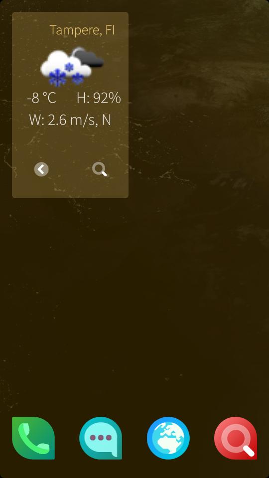
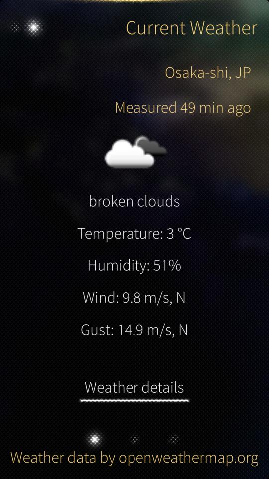
When I got my device, there were no weather apps so I decided to write one. It utilizes the Openweathermap.org free API. Screenshots below:

[ add comment ] ( 2082 views ) | permalink | print article |


 ( 3 / 2355 )
Since last blog post a lot has happened. First off, I was really busy for the few last months writing my master's thesis, so I haven't progressed on my OS or other projects at all. But finally, I got everything worked out and I graduated as M.Sc. in electrical engineering on 2013-12-04. After that, I have picked up the OS book again to continue the challenge.
So, last time I was trying to use GNU tools only for the projects in the book. After the break I felt that I was going nowhere with that and decided to go with the tools provided with the book for now. That way I could learn about programming OSses and could learn how to compile it on more general tools later (since compiling is the boring part anyways).
To use the precompiled tools, I only had to do some adjustments to the Makefile of the project, to use wine and replace some copy commands with GNU/Linux alternatives. Then I readily went onwards to do some graphics using the basic VGA, 8-bit 320x200 mode. (the book goes for the graphics first, since, well, it's fun to see the results on the screen and learn the smaller details on the way).
After setting up the palette, I made some simple line and square drawing. One of the interesting things there was how to draw lines, so I headed to wikipedia and found an usable algorithm, called the Bresenham's line algorithm, and it was easy to understand and implement in C by looking at the pseudocode.
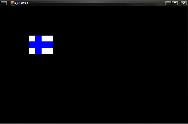
Here's a screenshot of the program drawing the Finnish national flag, paying respect to the indepence day on 6th December:
[ add comment ] ( 1598 views ) | permalink | print article |


 ( 3 / 2533 )
While I was in Japan, I found this very nice book (in Japanese), which I didn't buy there since it was quite heavy..
After getting back to Finland, I tried to find such a book in English, but couldn't find one really, so I ordered the book from Japan.
It is written in very informal style, like teacher informally chatting with the student, which makes it very easy to read and easy to approach. All in all, I really like it!
However, the thing is it is mainly targeted for windows user, which is why it comes with a CD-ROM with customized compilers and assember for the project. Since I'm running Linux as my work OS, I wanted to do it with the tools existing for linux, that is GCC and GAS (GNU Assembler), dd and the like. I felt that, since these tools already exists, I should learn to use them rather than some customized tools that are harder to get. There is support page for the book, which has some tips for following the book on Linux. That is wonderful, though most of it is not quite what I want, for example they are compling the customized tools for linux or just usin WINE for the task.
So, hopefully I will be writing here about some endeavors I've faced. I have already started working on this.
See you next time!
[ add comment ] ( 3710 views ) | permalink | print article |


 ( 3 / 2611 )
There is this one course project we were doing. Since we specified the board quite small, so we decided to order the board from a manufacturer, since we found one cheap enough for our budget. We waited for 3 weeks for the boards to arrive. It was then 3 weeks before the deadline.
We happily went to reflow lab to solder the components. everything seemed fine and cool first, until we found out several components had footprints of wrong size. There had been some mistakes when making the footprints, particularly someone misunderstanding MSOP8 for SOP8 and reversing battery holder's pins. That was still doable, few jump wires, problem solved. But there was something more...
I had found a library of avr 32-bit chips, symbols correct, footprint seems legit, alright, let's use this! is what I thought at that time. However, after using 10 hours to hack 40+ jump wires of width 0.2 mm, length less than 1 cm connect a 64-pin TQFP packaged chip on the board, I was cursing my stupidness.
The package was TQFP 64 alright. Just that it was smaller than any other TQPF 64 package I had seen before. And, oh yes, checking the datasheet told me it was indeed TQFP 64 and some letter combination I had not seen before. Checking further, I found the footprint on the datasheet, clearly showing the rigth size. Apparently the library I had used was outdated.
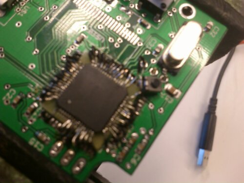
After 10 long hours, this resulted.
Okay, I guess everyone got the lesson. Always check the footprints, no matter how proper the libraries seem. Plan your schedule so that you have time for mistakes. Double check footprints. You'll save time doing that. There were some benefits in this too though. I learned how to solder damn small pins for instance. And everyone seeing the jump wires was like wow, how the hell did you manage to solder that? And of course, my patience got considerable boost enduring those 10 hours, resoldering after accidentally removing few of the wires I just had soldered.
That's all, happy checking, everyone!
[ add comment ] ( 4176 views ) | permalink | print article |


 ( 3 / 2382 )
Hello everyone, I got my headset mod ready few days ago (finally) and here's kind of a report of the process.
It all started with this Logitech Clearchat Wireless headset:Few years old headset, casing and frame was crumbling apart.
This headset, also known for a design mistake which causes the left headphone to cut and eventually go silent (it's just wire wearing and getting cut, see this), is quite good in terms of audio quality. So it would have been shame to throw it away, despite it was already old and I could've afford a new pair (from some other manufacturer). Since I had already opened it up a few times fixing the cutting left phone I had some kind of idea what was inside, so I decided I'd find some cheap wired headset and put the electronics from the old one inside the new pair. Time flew and I just couldn't find suitable headset, until I looked at the Peltors below on another occasion. They were soundproof, had lot of space inside and were relatively cheap.
Peltor ear protection set disassembled.So the project started slowly to proceed. I had already most of the tools:
Soldering iron
Drill with grinding heads
Small vise
Various screwdrivers
And that was about it. Some small stuff like wires, connectors and glue was also needed.
Here's some pictures of the old headset being opened up:
The PCB is pretty dense on components and since you only have the silkscreen markings it's quite a pain to figure what goes where, since it's a 4-layer board. I just used a multimeter to find out how the 8-pin connector (on top, white block) connects to some places which are easier to solder without fear of short-circuits.
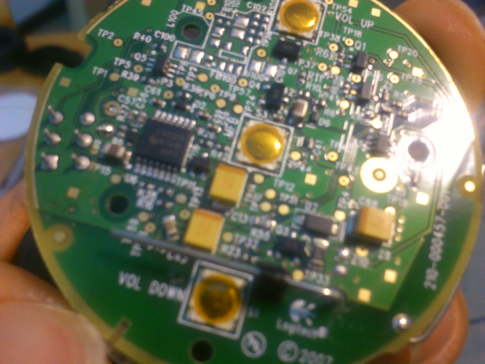
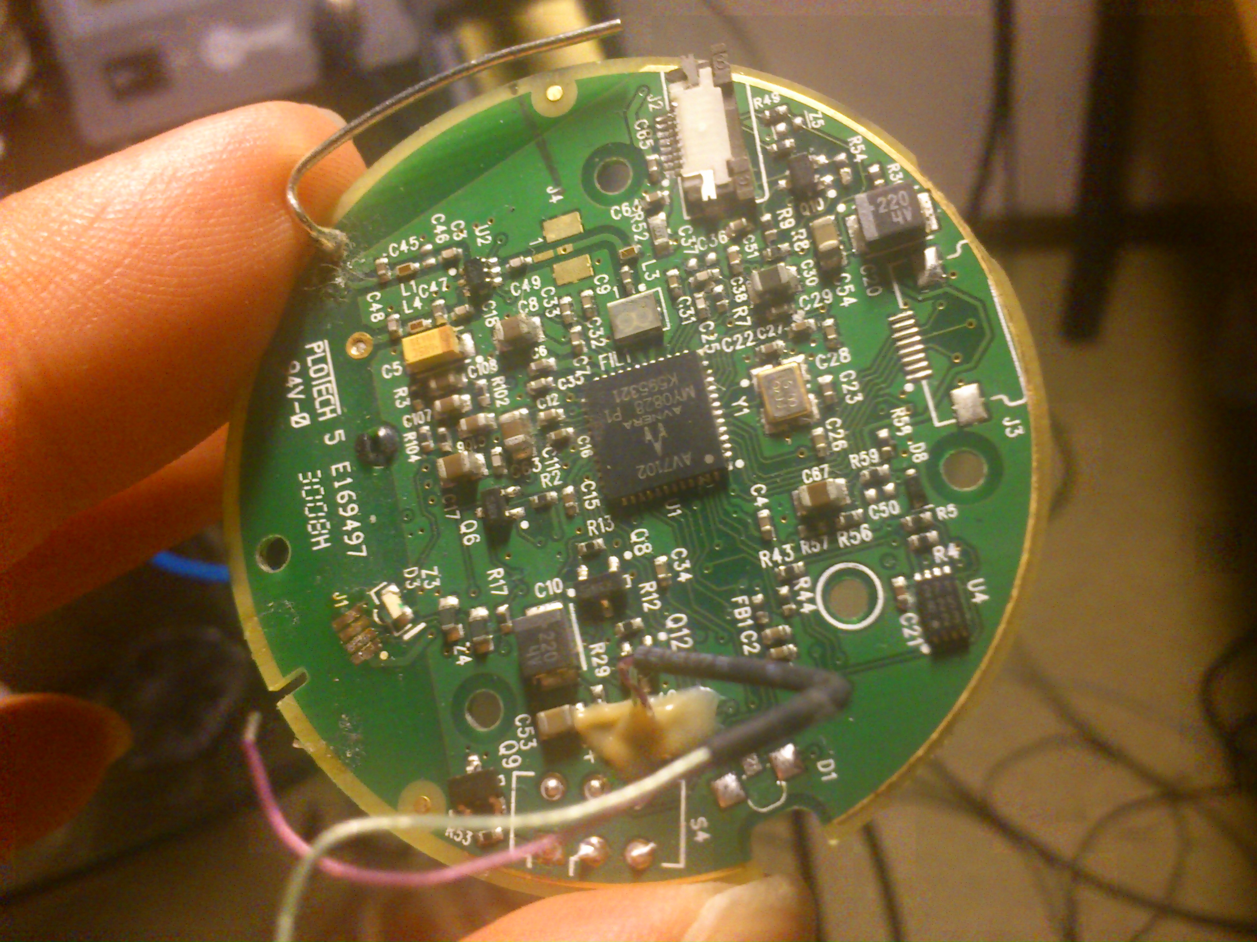 the other side of the board there was number of test points, labeled "TP#", and most of the connectors pins were connected to one of the test points.
 The right headphone side is much simpler, since there is basically no electronic components there, just wires connecting.
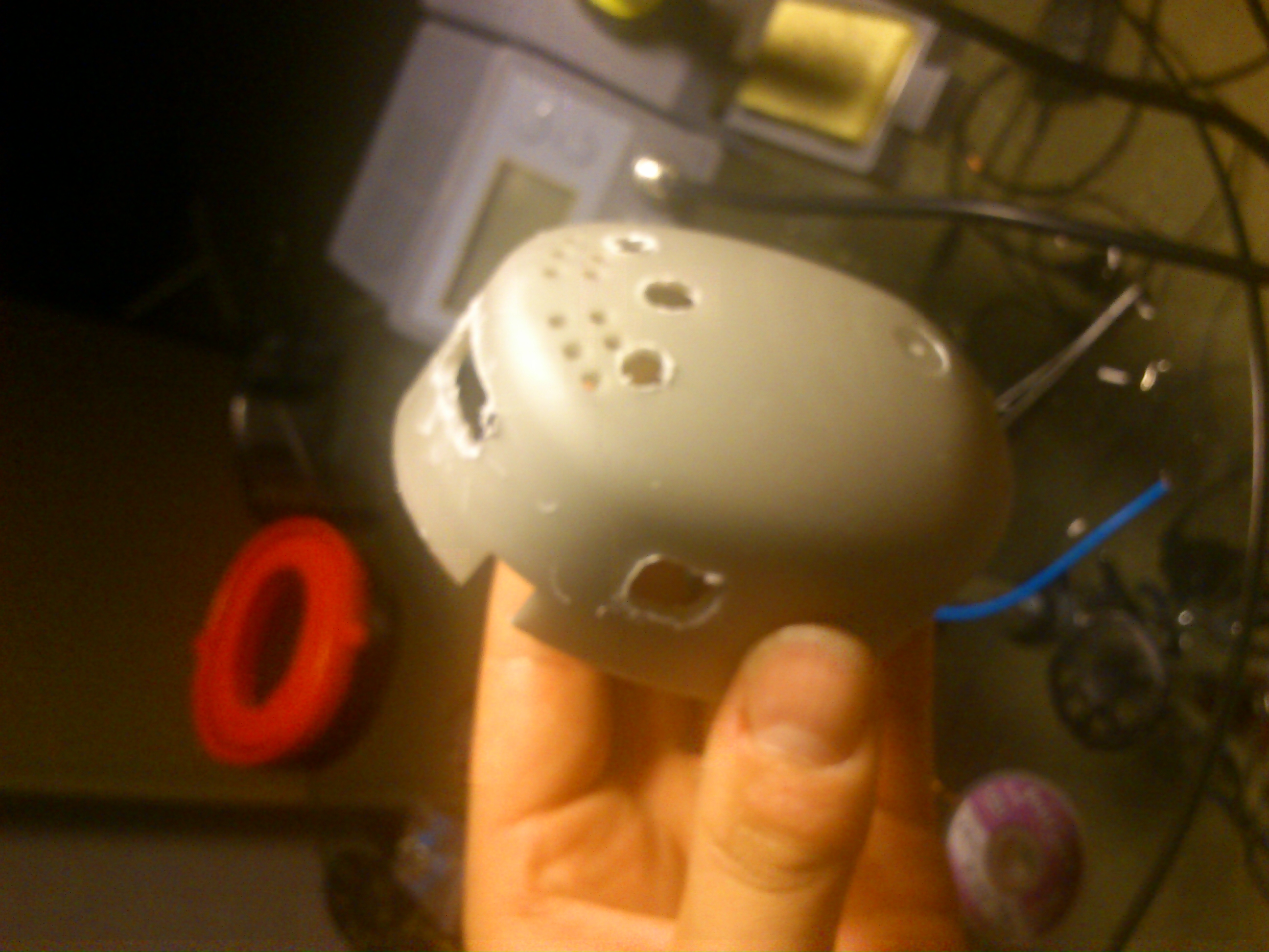
The ear protector cups had two layers, which was a challenge but also a boon, since I could attach buttons and connectors to the inner layer so they are firmly there and don't give in when trying to push the connectors together.
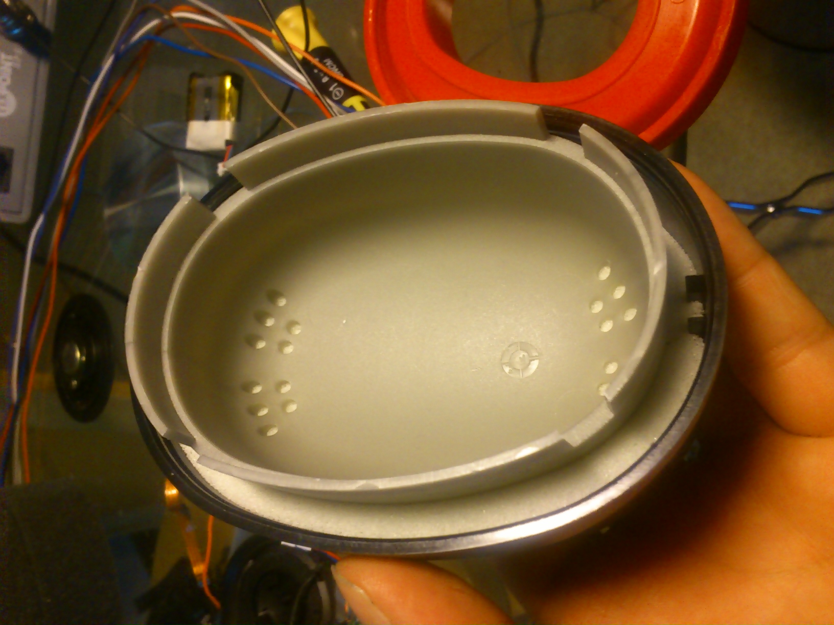 I modified the ear cups by drilling holes for wires and buttons and connectors like below:
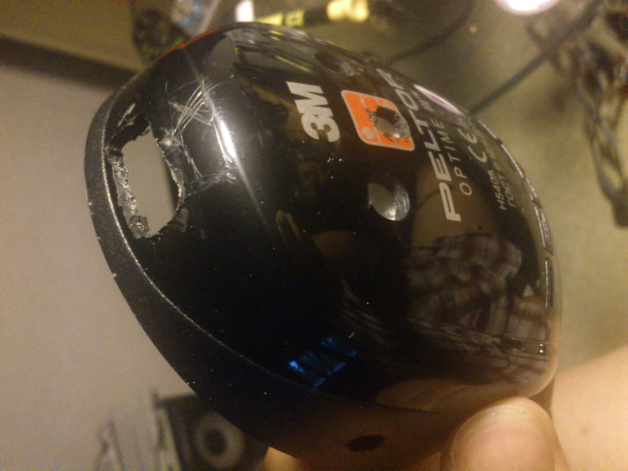
So, after testing out the correct connections, I replaced the flat connector with a general pin header with individual wires soldered and twisted around each other. Unfortunately, the microphone stopped working for some reason, I might have connected some voltage inversed to the mic which broke it. I gave up on it, since it was rather impossible to debug it without an oscilloscope. So I put the rest together, and got rather nice wireless headphones instead of a headset.
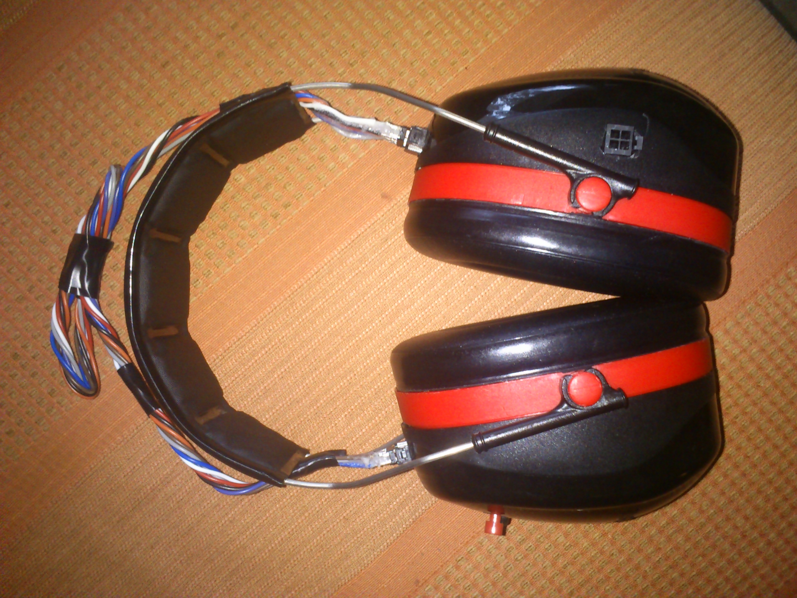 During the process I learned much about what should be taken into account when designing how to fit electronics into their casing. I made a lot of mistakes and hopefully won't make them next time. I'm thinking about making my own electronics for version two, using bluetooth or something as wireless solution, maybe trying to fit it into something smaller than these Peltors.
If you want any details just ask for them, I might make a more detailed post later too, about the wiring and such.
[ add comment ] ( 15628 views ) | permalink | print article |


 ( 3 / 2222 )
 Calendar


